Why Connector Pin Quality Needs a Defined Inspection Method
A connector pin may look simple, but small dimensional differences or surface conditions can matter to the way a component fits and performs in its assembly. When inspection depends mainly on manual visual checks, results can vary with operator experience, viewing angle and production workload. As output increases, it can become difficult to maintain the same inspection routine for every part.
An automated vision inspection process provides a structured way to capture images and compare selected features with predefined criteria. The goal is not simply to add cameras to a production line. It is to define which characteristics matter, how each characteristic will be viewed and what result should trigger acceptance or rejection.
What Should Be Checked on a Connector Pin?
The inspection plan should start with the engineering drawing and the customer’s quality requirements. For the connector pin shown in the demonstration, the video identifies multi-segment outer-diameter checks and surface appearance inspection. It also shows image views associated with hole-related features. These are useful starting points for defining an inspection recipe, but they should not be treated as a complete defect list for every pin design.
For each target feature, manufacturers should specify its measurement location, tolerance, acceptable visual variation and the conditions under which a part is considered nonconforming. Representative samples are essential. They help the engineering team distinguish real defects from normal process variation and confirm that the system is evaluating the correct areas.
Why Use Multiple CCD Camera Views?
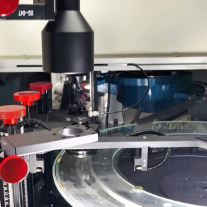
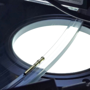
A single camera view may not show every relevant surface or dimensional section of a precision pin. The RKE video identifies 7 industrial CCD cameras in the demonstrated configuration. Multiple camera positions can capture different views of the component, while the lighting arrangement helps reveal the selected edges and surface details.
The appropriate camera count and orientation depend on the part’s length, stepped geometry, target features and required coverage. More cameras do not automatically mean better inspection. Each view should have a clear purpose, and the full setup should be validated with real samples.
How to Evaluate the Inspection Software
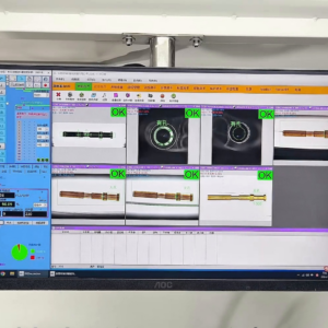
The video shows a monitoring interface with several image windows and OK indicators. This type of display allows operators and engineers to review the configured inspection views and their current results. During acceptance testing, the team should compare system decisions with manually verified samples, paying attention to missed defects, false rejects and parts that require a second review.
The inspection recipe should document the criteria for OK, NG and uncertain results. It should also define how rejected parts are separated and how inspection records are reviewed. Clear rules make the process easier to validate and maintain when product specifications or production conditions change.
Performance Figures: What Do They Mean in Practice?
For this video demonstration, the stated detection speed is 120 pcs/min and the stated detection accuracy is ±0.01 mm. These figures describe the demonstrated setup. They should be verified for the customer’s actual component because part dimensions, tolerance bands, surface finish, feeding stability, lighting and inspection logic can all affect performance.
A useful sample test should therefore record both throughput and inspection results. Testing only at the target speed may overlook detection issues, while testing only at a slow speed may not reflect real production conditions. The acceptance plan should reproduce the expected operating environment as closely as possible.
Questions to Prepare Before Requesting a Solution
- Which dimensions and surface features are critical on the current connector pin drawing?
- Are there known good and defective samples available for testing?
- Which hole-related or appearance conditions must be identified?
- What production rate and part presentation method are required?
- How should the system handle OK, NG and uncertain inspection results?
Discuss Your Connector Pin Inspection Requirements
The most reliable way to evaluate an automated connector pin inspection machine is to begin with the actual component and its quality requirements. Drawings, sample parts and clearly defined defect criteria help determine the camera views, lighting and inspection logic needed for the application.
DongGuan RKE Intelligent Technology Co., Ltd. develops machine vision inspection and sorting solutions for industrial components. Contact the RKE team to discuss sample testing and a suitable inspection configuration.