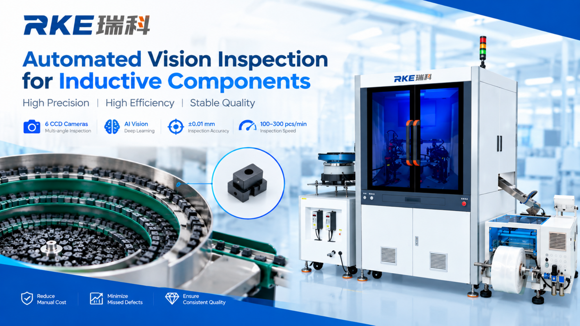
When small inductive components move through a high-volume production line, visual inspection becomes more than a simple appearance check. The system must present every part consistently, capture the required views and make a repeatable decision against defined quality criteria. This RKE application combines controlled feeding, six CCD cameras and AI vision software to create an automated screening process.
From Random Parts to Controlled Presentation
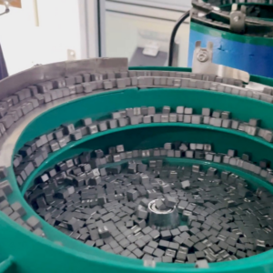
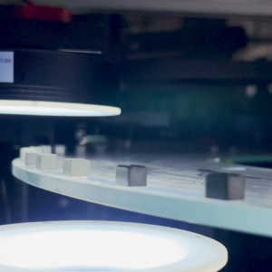
Manual inspection can become difficult when components arrive continuously and at high speed. The first step is therefore stable product presentation. A vibratory disc feeder separates and guides the components into the inspection path, helping maintain a consistent position before image capture.
Why Multiple Cameras Matter
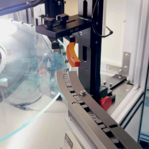
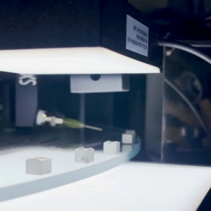
Different inspection points often require different viewing angles. Six CCD industrial cameras are arranged around the inspection area so the system can capture the necessary views while the parts travel through the machine. This multi-view structure supports more complete visual coverage than a single-camera arrangement.The inspection station uses multiple CCD cameras to capture components as they pass through the vision system.
Turning Images into Production Decisions
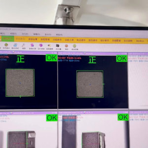
The camera images are analyzed by AI vision inspection software. The software interface shows inspection results for individual parts and identifies OK and NG conditions. In a production environment, this provides a direct connection between image acquisition and quality classification.
Inspection Criteria Follow the Customer’s Requirements
The application focuses on practical appearance requirements rather than a generic defect list. The demonstrated inspection checks whether the product has been painted and looks for visible conditions including dark cracks, damage, missing corners and dirt. Defect definitions can be configured around the actual acceptance criteria of the product and production process.
Speed and Accuracy in the Demonstrated Application
The video shows a displayed inspection speed of 300 pieces per minute and a displayed detection accuracy of ±0.01 mm. These values should be treated as application-specific demonstration results. Final performance depends on product size, material, surface condition, defect definition, camera and lighting configuration, and the required inspection standard.
What Automated Screening Changes on the Production Floor
An automated inspection system can make the inspection process more consistent by applying predefined criteria to every detected part. It also creates a clearer production workflow: feed the component, capture the required images, analyze the result and classify the product. This structure is particularly useful when manufacturers need repeatable quality control for large production volumes.
A Flexible Solution for Component Inspection
The right machine vision configuration depends on the product rather than on a fixed camera count or inspection template. RKE can develop the feeding, camera arrangement, lighting, software logic and sorting method around the customer’s component and quality requirements. For manufacturers evaluating automated inspection, a sample test is an effective way to determine the appropriate configuration and expected performance.