Why Inspect the Whole Part, Not Just One View?
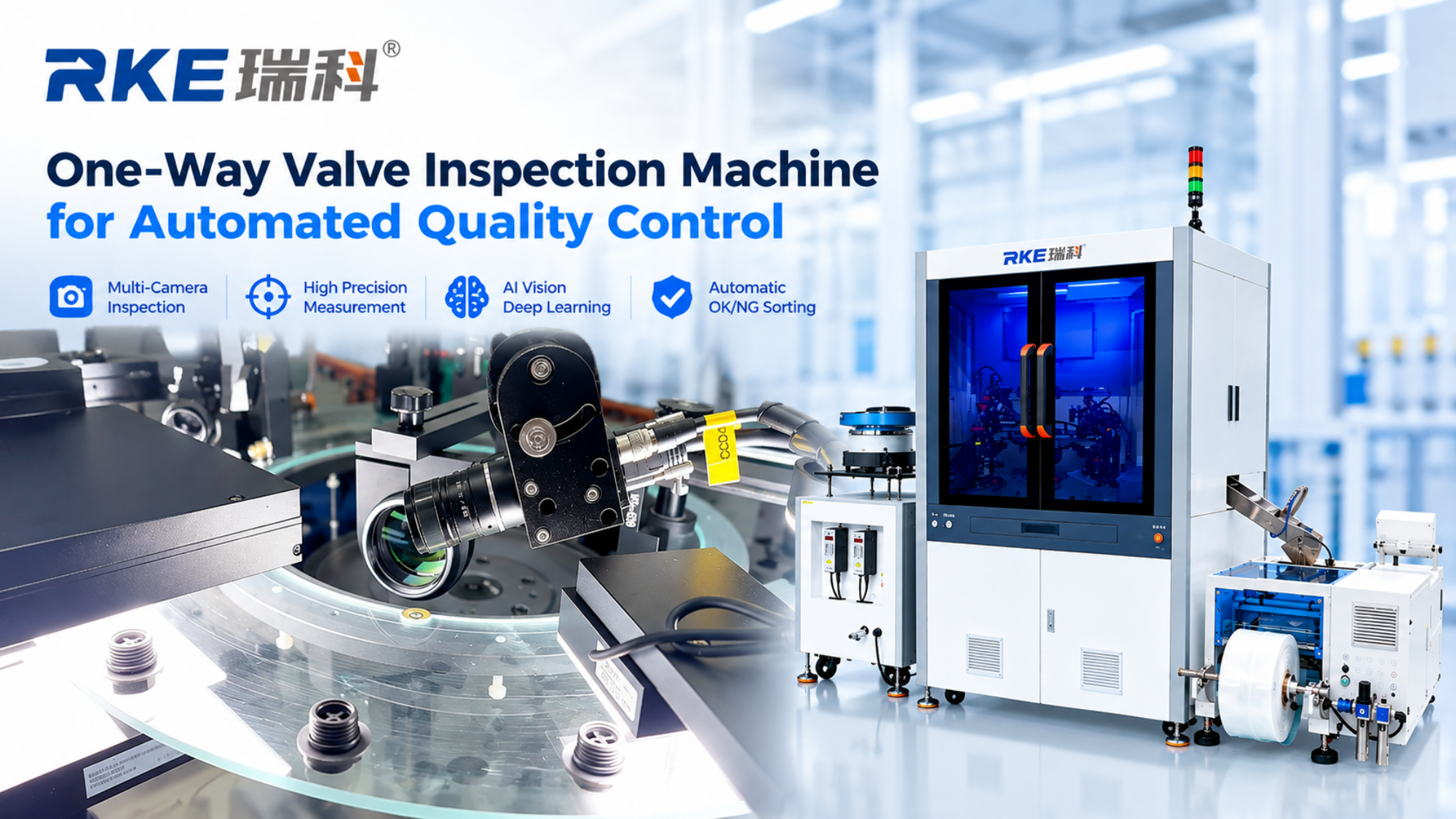
A valve component can pass one visual check and still have a problem elsewhere. A dimensional deviation, a surface mark or an abnormal feature may appear in a different area of the part. For this reason, the inspection plan should begin by listing the critical dimensions and visible defects that matter to assembly and product performance. The RKE one-way valve application demonstrates how multiple camera views can bring these checks together in a single line.
Step 1: Present Each Component Consistently
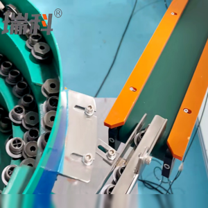
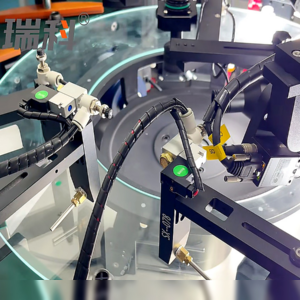
The vibratory bowl feeder organizes loose components and guides them toward the inspection station. Consistent feeding helps reduce overlap and unstable positioning, both of which can affect image quality. A well-designed feeding path is therefore part of the inspection solution, not just a way to move parts.
Step 2: Capture Different Views with CCD Cameras
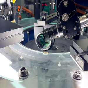
Eight sets of CCD industrial cameras are shown in the demonstration. Each view can focus on a specific inspection area, allowing the system to evaluate more than one visible face or feature. Camera placement and lighting should follow the geometry of the actual part; more cameras alone do not guarantee better inspection.
Step 3: Measure Critical Geometry
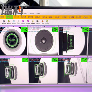
The video shows dimensional checks for overall length and width, along with views for height and inner-diameter features. The vision software extracts the relevant geometry from each image and compares it with the configured limits. For a production project, the measurement method should be validated against the product drawing and reference samples before the line enters routine operation.
Step 4: Evaluate Surface Conditions
The inspection plan can also include defined surface abnormalities on the top and bottom of the component. AI deep-learning tools can help classify image patterns, but the result depends on representative training samples, stable illumination and a clear definition of acceptable versus defective parts. For that reason, defect samples should be reviewed with the customer during setup.
Step 5: Classify and Route OK/NG Parts
After processing the captured images, the system assigns an OK or NG result and routes each component through the automated output process. The software screen also shows inspection counts and result summaries, helping operators monitor the process and review abnormal trends..
What Do the Demonstration Figures Mean?
The video displays up to 200 pcs/min and approximately ±0.01 mm inspection accuracy for the demonstrated application. These figures should be treated as application-specific reference values. Before specifying a target for another component, confirm part dimensions, defect size, required false-reject and missed-defect rates, feeding method and camera configuration through sample testing.
Planning a Similar Valve Inspection Project
Before selecting an automated system, prepare the product drawing, OK and NG samples, a list of critical dimensions, defect examples and the target production rate. This information helps determine camera views, lighting, measurement methods and sorting requirements. A feasibility test can then establish whether the proposed setup meets the required inspection criteria.
Conclusion
Automated one-way valve inspection combines stable feeding, multi-view image capture, dimensional checks, surface analysis and OK/NG sorting. When the inspection plan reflects real product risks, machine vision can make quality checks more repeatable and easier to monitor on the production line.