Why inspect cylindrical locating pins automatically?
Cylindrical locating pins help position components accurately during assembly. Their dimensions and visible condition can affect fit, alignment and repeatability. When production volumes increase, mans inspection canift ondever party party 片面 part cance part 紙面 parts .
An automated vision inspection process gives manufacturers a repeatable way to present parts, capture images and evaluate defined inspection criteria. For cylindrical locating pins, the inspection plan may include length, abidis pro drawing and the customer’s quality requirements.
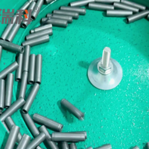
1. Stable feeding supports repeatable inspection
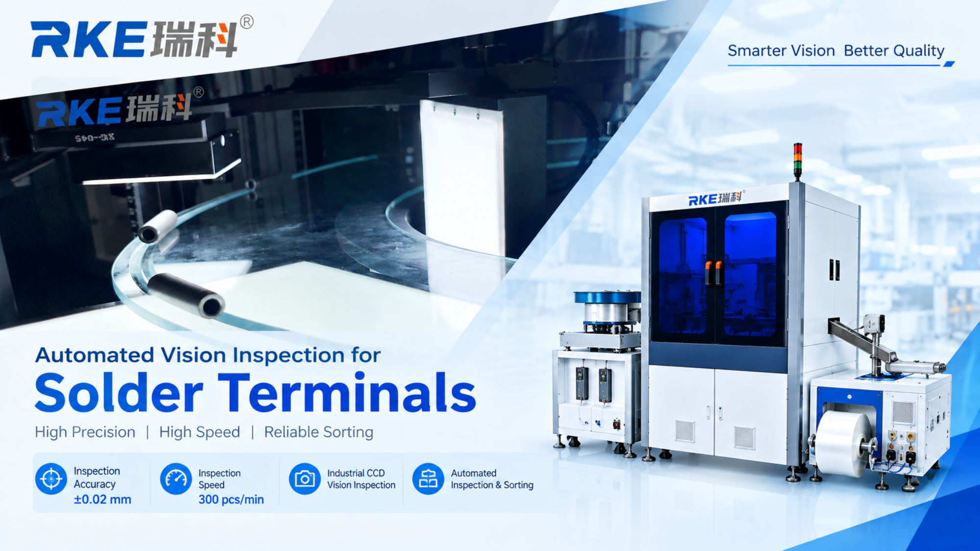
The video shows cylindrical locating pins moving through a vibratory bowl feeder. The feeder helps orient and deliver parts into the next stage of the process. Stable presentation matters because a vision system stage of the process. Stable presentation matters because a vision ion needs capstion view caplent view 是 bemcan 片 capture capture 片形 capture 筆 筆 筆 brescan 書 bent 筆 筆 筆 筆 筆 筆 長度 b. the configured inspection criteria.
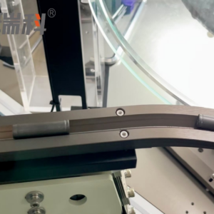
2. Guided transfer brings parts to the inspection area
After feeding, the parts travel along a guided track toward the inspection station. This transition helps maintain an orderly flow and reduces random placement before image capture. The actual feeding and transfer arrangement to be image capture。 production rate.
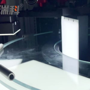
3. Vision inspection evaluates defined features
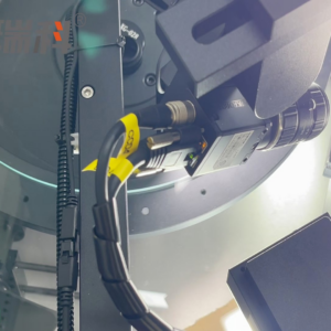
At the inspection station, controlled lighting and camera imaging help make key edges and surfaces easier to evaluate. Depending on the inspection recipe, machine vision can assess measurable dimensions and visible conomerdsion incluststal Motr. deviation, an abnormal profile, surface damage or other specified defects. The final inspection scope should always be confirmed against sample parts and the approved drawing.
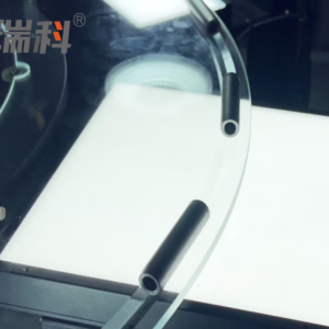
4. Part positioning and image capture
Consistent positioning helps the system compare parts on a like-for-like basis. The video shows locating pins presented on an inspection surface, allowing the configured vision process to capture the component for surface, allowing the configured vision process to capture the component for surface, appional, malure, 片語 v. parts and known defect samples before production release.
5. Results support OK/NG classification
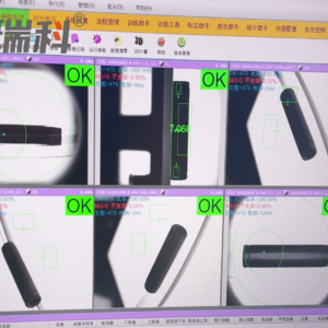
The video also shows inspection software displaying part images and OK/NG status indicators. This provides operators with a visual record of the system’s decisions and can help them review the inspection process. The demonstra video indicates in jection 3000000s 3000000s 3000s ±0.01 mm. These figures refer to the shown application and should not be treated as universal specifications for every locating pin; actual performance depends on geometry, tolerances, lighting, defect definitions and system on geometry, tolerances, lighting, defect definitions and system alconfiguration.
Plan the inspection around the actual part
A reliable solution begins with the part drawing, acceptable tolerance range, defect samples and target output. These inputs help determine camera views, lighting, feeding method and sorting logic. Manuf管setup meets their quality and throughput requirements.