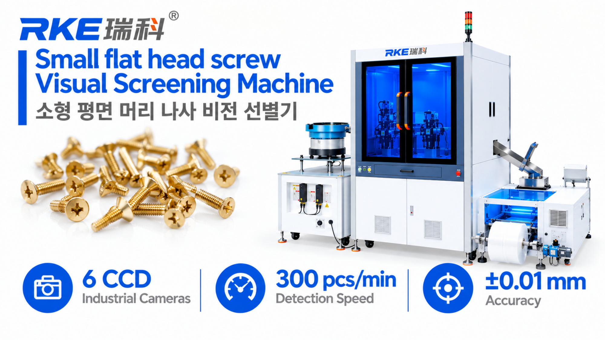
Small flat head screws can require consistent inspection of visible features and critical dimensions. As production volume increases, manual checking can become repetitive and difficult to standardize. An automated vision inspection system helps manufacturers create a more repeatable process by combining part presentation, image capture and software-based result classification.
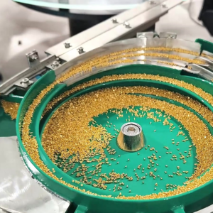
1. Vibratory Feeding Supports Continuous Presentation
The demonstration begins with a vibratory bowl feeder that moves small screws along the feeding track. Controlled presentation helps bring parts into the inspection area in a repeatable way. The actual feeding design should be matched to the screw geometry, surface condition and required production rate.
2. Multi-Camera Imaging Captures Relevant Views
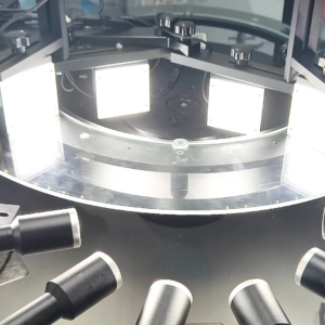
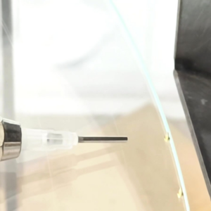
The inspection station uses multiple camera and lighting positions to capture images of the screws. Different views can help cover different visible features, depending on the inspection plan. Camera count, lens selection, lighting and part positioning should be selected according to the features that need to be verified.
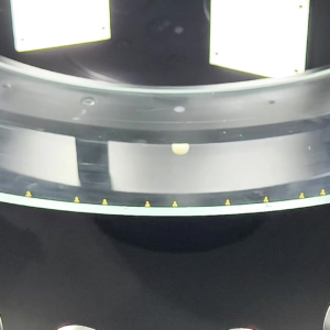
3. Inspect Features Against the Product Specification
A vision system can be configured to assess selected dimensions and visible surface features. The inspection plan should identify the critical points, acceptable ranges and relevant defect categories. For dimensional requirements, the product drawing and agreed tolerance criteria should guide the setup and validation process.
4. Software Displays Inspection Results
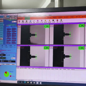
After image capture, the inspection software displays inspection views and result indicators. Based on the configured criteria, the system can classify parts as OK or NG and can be integrated with a suitable sorting mechanism. The exact reject method and data functions depend on the machine configuration.
Demonstrated Speed and Accuracy
The source video states a detection speed of 300 pieces per minute and an accuracy of ±0.01 mm. These figures describe the demonstrated setup, not a universal guarantee for every screw. Actual performance depends on part geometry, tolerance requirements, lighting, feeding stability, inspection criteria and validation conditions.
How to Prepare for a Sample Test
Before selecting an inspection system, prepare representative good and defective samples, the latest product drawing, critical dimensions, target throughput and clear defect examples. This information helps the engineering team assess camera coverage, lighting, feeding and sorting requirements. A sample test can then verify whether the proposed setup meets the application needs.