Why Consistent Inspection Matters
Pipe fittings must meet the requirements defined for their applications. Depending on the design, key checks may include specific dimensions, visible surface conditions, and conformity to product drawings. However, manual inspection can be difficult to standardize when parts move through production at a steady pace.
An automated vision inspection system helps manufacturers establish a repeatable inspection process. First, the system presents each part to the cameras under controlled lighting. Next, the software captures images and compares visible features against predefined inspection criteria. As a result, manufacturers can improve inspection consistency and streamline quality control.
1. Vibratory Feeding and Guided Transfer
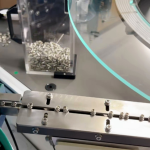
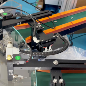
First, a vibratory bowl feeder moves pipe fittings toward the inspection station. Then, a guide track arranges and transfers the parts into the machine. Consistent part feeding is essential because the position and orientation of each fitting directly affect the inspection images.
2. Multi-Camera Image Capture
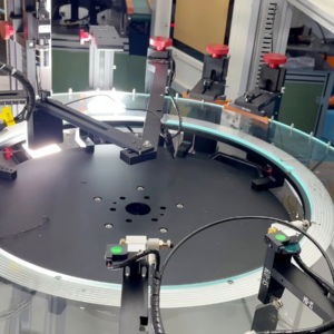
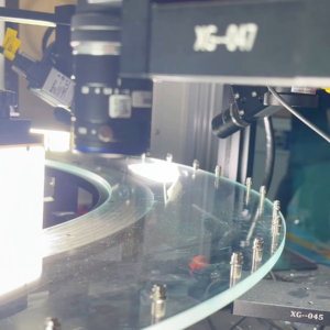
Next, the system uses an eight-CCD-camera configuration, as shown in the demonstration. Multiple camera views help the system inspect different sides and features of each component. In addition, engineers can adjust camera positions and viewing angles to match the fitting geometry and inspection requirements.
3. Inspect Dimensions and Visible Defects
After image capture, the inspection software evaluates product dimensions against drawing requirements and checks visible appearance. Depending on the component and validated setup, the system can inspect selected dimensions and identify defined surface defects. Therefore, manufacturers should establish the inspection scope in advance instead of assuming that one configuration can detect every possible defect.
4. Review Results and Discharge Parts
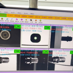
Once the software completes its analysis, the inspection interface displays captured images and OK/NG indicators. The system then classifies each part according to the configured inspection criteria. Finally, the machine discharges the inspected parts onto a conveyor for the next production step.
Demonstrated Performance
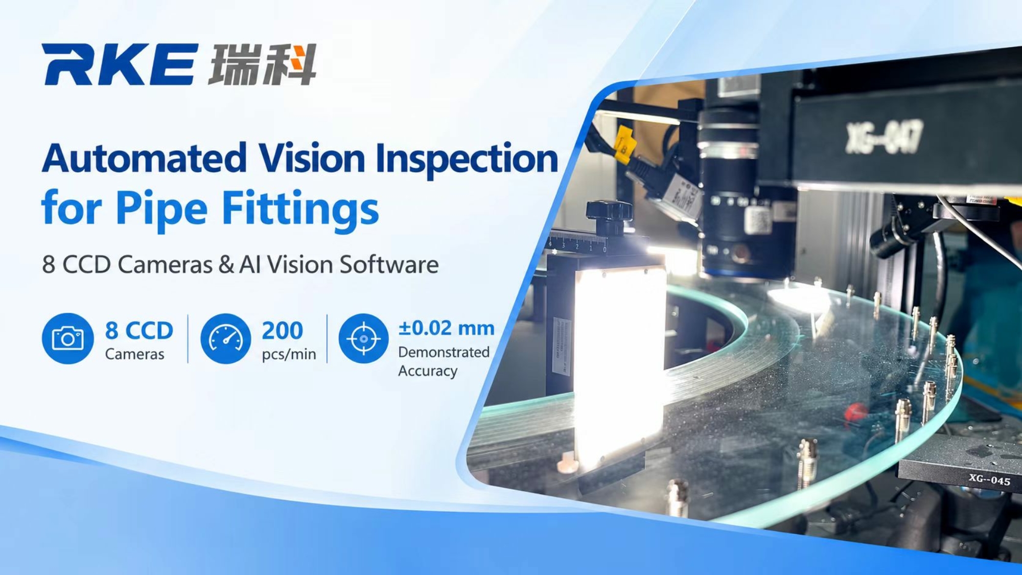
The demonstration shows a detection speed of 200 pieces per minute and a stated inspection accuracy of ±0.02 mm. However, these figures apply to the demonstrated setup and do not represent universal performance guarantees. Actual results depend on several factors, including component geometry, tolerance requirements, lighting conditions, feeding stability, inspection criteria, and the validation method.
How to Prepare for a Sample Test
To evaluate feasibility, start by preparing representative accepted and rejected samples, the latest product drawing, critical dimensions, target throughput, and examples of relevant defects. With this information, the engineering team can define camera coverage and inspection criteria more accurately. Subsequently, a sample test can verify whether the proposed configuration meets your production requirements.