Why Plastic Buckle Inspection Needs Consistent Criteria
Plastic buckles and snap-fit components are small parts, but their geometry can be important to assembly and retention. Depending on the design, manufacturers may need to check dimensions, molded features, and visible defects that could affect fit or function. Manual checks can be difficult to keep consistent when many components move through production.
An automated vision inspection process helps standardize how parts are presented, imaged, and evaluated. The inspection plan should be based on the product drawing, agreed tolerances, and representative examples of acceptable and defective parts.
1. Vibratory Feeding for Continuous Presentation
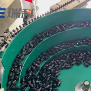
The demonstration begins with plastic buckles in a vibratory bowl feeder. The bowl organizes components and moves them toward the inspection area. Consistent feeding helps reduce variation in how parts arrive at the cameras, although the exact feeding setup must be matched to the part shape and production conditions.
2. Multi-Camera Image Capture
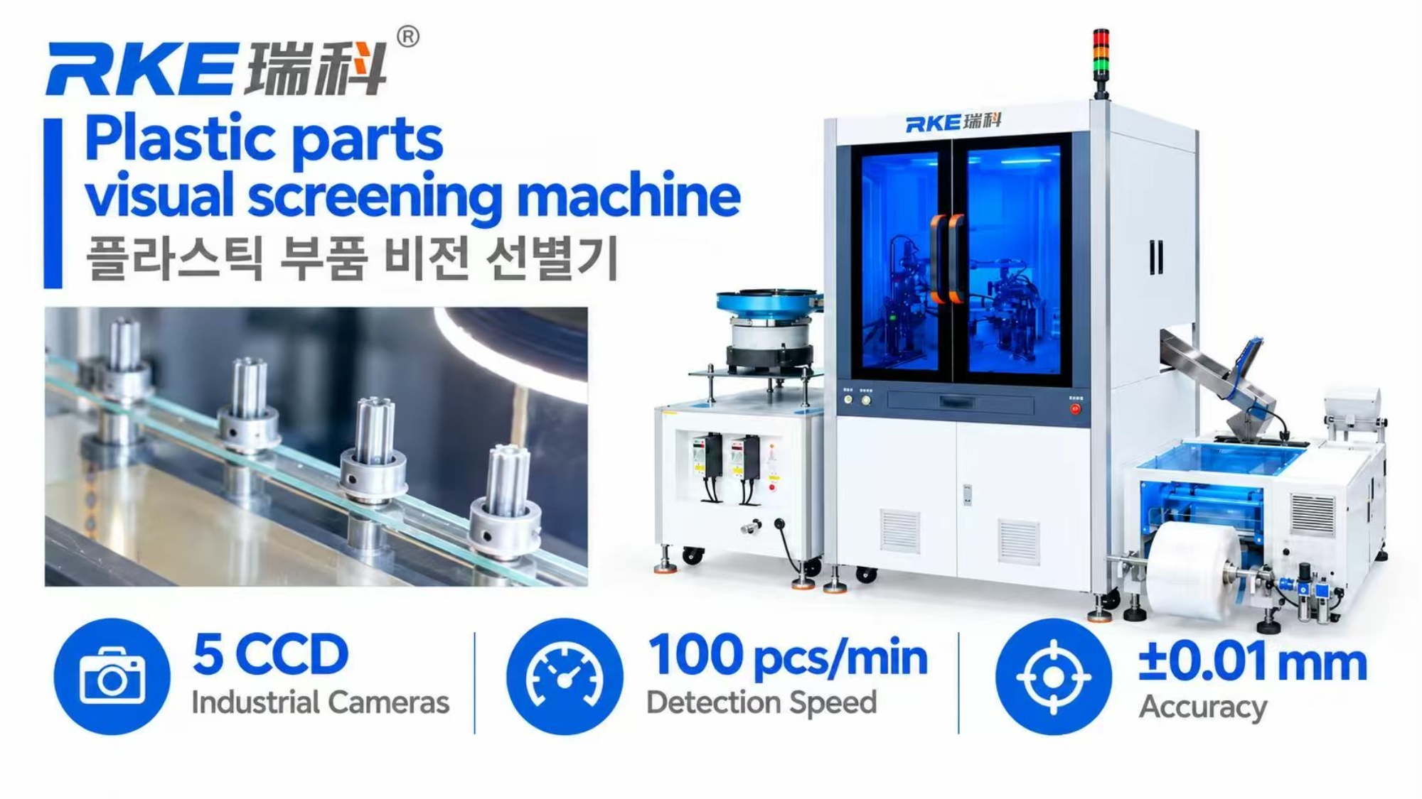
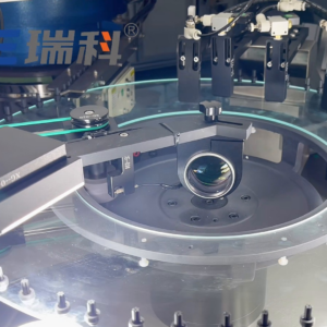
The video describes a configuration using five sets of CCD industrial cameras. Multiple views can help the system inspect selected features from different directions. Camera count alone, however, does not define inspection capability; camera positions, lens selection, lighting, part orientation, and the inspection criteria all need to be considered together.
3. Check Defined Dimensions and Molded Features
The video describes checking product height and outer diameter according to customer requirements. It also shows inspection questions related to molded steps and snap-fit features. These checks should be configured around the drawing and verified using real samples. Any additional dimensions or defect types should be confirmed during the application review rather than assumed.
4. Software-Based Evaluation and OK/NG Results
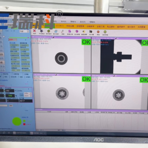
The software screen shows multiple inspection views and result indicators. After image capture, the system evaluates the visible features against the configured criteria and displays the result. An automated inspection project should define how OK and NG parts are classified, how borderline results are handled, and how rejected parts are separated downstream.
Demonstrated Speed and Accuracy
The video states a detection speed of 100 pieces per minute and an accuracy of ±0.01 mm. These are figures shown for the demonstrated setup, not universal guarantees for every plastic buckle. Actual throughput and measurement performance depend on component geometry, tolerances, feeding stability, lighting, defect definitions, and validation conditions.
How to Prepare for an Inspection Test
For a useful feasibility assessment, provide the latest product drawing, representative good parts, examples of defects to detect, critical dimensions, and target production rate. This allows the inspection criteria and camera coverage to be reviewed against the actual application before the system is approved for production.
Learn more about RKE machine vision inspection solutions.