Why pin inspection needs more than a quick visual check
Pins are often small, but their quality can have a direct effect on fit, positioning and assembly. A part that falls outside the drawing requirement or carries a visible surface defect may cause problems later in the manufacturing process. When inspection relies only on manual visual checks, consistency can become difficult to maintain as output increases.
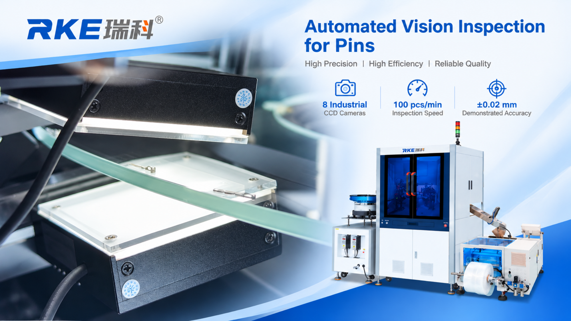
Automated visual screening offers a more structured way to present parts, capture images and evaluate selected characteristics. The RKE pin inspection demonstration shows a vibratory feeding section, a circular inspection platform, multiple camera assemblies and a software interface for reviewing inspection results.
Step 1: Keep parts moving in a controlled way
A stable inspection process starts before the cameras take an image. The vibratory bowl feeder shown in the video organizes the pins and supplies them to the inspection section. Consistent feeding helps reduce interruptions and supports repeatable part presentation.
During a feasibility test, manufacturers should check whether parts feed smoothly without excessive overlap, jamming or unwanted orientation changes. These details help determine whether the feeding arrangement suits the actual component.
Step 2: Capture the features that matter
The video identifies **8 industrial CCD cameras** in the demonstrated system. Multiple camera views can help inspect different sides or features of a pin, depending on the part design and camera arrangement. The inspection plan should specify exactly which dimensions and appearance conditions need to be checked.
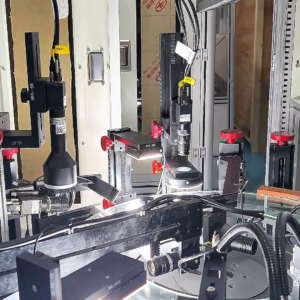
For example, the video describes checking key dimensions against drawing requirements and reviewing appearance conditions such as deformation and surface scratches. The final inspection scope should be agreed with the customer and verified with real samples; not every defect type is automatically covered by every camera setup.
Step 3: Review image results and set clear OK/NG rules
The vision software shown in the demonstration displays several captured images with OK indicators. This interface helps operators review the configured inspection output. However, an OK label is meaningful only when the inspection criteria have been defined and validated.
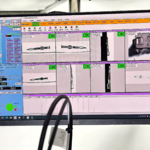
Before the system enters routine production, compare its decisions with manually classified samples. Confirm how the system handles borderline parts, uncertain images and confirmed defects. Clear OK/NG rules make the inspection process easier to evaluate and maintain.
What performance figures does the video show?
For this pin visual screening application, the supplied video states **100 pcs/min** and **±0.02 mm** detection accuracy. These figures refer to the demonstrated setup. Actual results may change with pin dimensions, tolerance requirements, defect definitions, surface finish, lighting, feeding conditions and production environment.
What should you prepare before requesting a solution?
A focused sample test is more useful than choosing equipment from headline specifications alone. Prepare the following information to help assess the application:
- Part drawings, dimensions and tolerance requirements
- Samples representing normal production variation
- Known defects and clear examples of acceptable parts
- The required inspection speed and production volume
- The required OK/NG output and rejected-part handling method